Translate this page into:
Determination of helmet CG and evaluation of neck injury potentials using “Knox Box criteria” and neck torque limits
Abstract
A military flying helmet, besides providing head protection serves as a mounting platform for display visors, Night Vision Goggles (NVGs), Oxygen masks and radio telephony that improve pilot performance during a mission. However, these systems may increase the potential for neck injury due to excess of head supported mass and/or altered combined head and helmet system Centre-of- Gravity (CG) while increasing moment at the head neck joint. In present study, a 50th %tile Anthropometric Test Dummy (ATD) head was developed to asses mass properties of mid size helmets of Mirage, Su-30, Mig21 (LWI) and Gallet assembly on a Trifilar Pendulum. The mass of the ATD head was 3.33 kg and CG from head anatomical origin was (0.28, -0.01, and 1.41cms). The mass of the helmets under study varied from 1.61 to 2.54 kg. The X and Z CG coordinates were between -0.04 to 0.85 cms and 2.45 to 3.22 cms respectively. The neck torque at C7/T1 juncture due to helmet weight and X coordinate CG shift varied from 29.24 to 78.40 N-cms. The mass moment at head neck joint was between 19.18 to 38.43 Kg-cm. None of the helmets breached the CG shift limit of the Knox-Box criteria. However, a neck torque value above 78 N- cm for Gallet assembly could adversely affect the wearer’s ability to identify and track targets and in addition could increase the neck fatigue under long duration whole body vibration (WBV).
Keywords
Flight helmet
Headform
Centre of Gravity
Knox-Box
Neck Torque
Introduction
Helmet-mounted devices (HMDs) such as NVGs, display visors, Oxygen masks and radio communication systems are designed to enhance pilot performance through improvements in situational awareness, night vision, target acquisition, and weapon delivery. While such HMDs indeed enhance performance there are concerns about the potentially adverse effects associated with these devices on helmet. As the number of features increased, so as the total weight of the system and this added weights of HMD’s forced pilots to modify their neck posture such that greater deviations from a neutral upright position was adopted. These neck posture deviations over a time period increased the stresses on the musculoskeletal system of the head and neck, increasing the potential for injury [1,2], While the total weight was important, another major factor in the injury potential was the location of the CG of the combined head and helmet system [3, 4, 5 & 6]. The CG location where entire mass of head is assumed to be concentrated is measured from anatomical origin of the head defined via intersection of the planes [7, 8], Adding mass to the head in the form of a HMD can move the combined head-helmet CG away from this ideal location and into unacceptable regions leading to potential for Determination of helmet CG and evaluation of neck injury potentials: Gaur et al injuries during dynamic events [9, 10 & 11]. The CG shifts, and increased loading on the neck and upper spine produced by HMDs results in excessive helmet motion relative to the head, neck muscle fatigue and in high G environments effects can range from neck strain to serious or fatal injury as well as possible long-term cervical and spinal degradation [12, 13 & 14]. The neck injury potential in helicopter crashes is due to force transmission from the vertical acceleration component, extreme head and neck motion which places the neck in hyperflexion and distraction, and neck compression and shear due to head contacts with instrument panels and cabin structures. Aviators flying rotary-wing aircraft are exposed to WBV, transmitted primarily through the seating system causing musculoskeletal stress to the back and neck [15]. These stresses are aggravated when the head is further loaded with HMDs.
Literature reviews have shown past research efforts concentrating on helmet weight relative to muscle fatigue in both normal and sustained-G flight environments. Lately, a sustained research has been initiated to examine the relationship between helmet inertial properties (CG and Moment of Inertia) and the biomechanics of the neck during the impact acceleration experienced during emergency ejection. The US Air Force in 1991 developed an “Interim head/neck criteria” on maximum head supported weight and altered CG in order to minimize neck injury during ejection [12, 16]. For ejection seats (ACES-II) with dynamic response Index (DRI) of 13 or less, acceptable helmets load was 2.27 Kg (5 lbs) and CG coordinate limits were defined by -2.03 to 1.27 cm the on the X axis and 1.27 to 3.81 on the Z axis. This spatial limit plot of CG coordinates on an X-Z plane yielding a rectangular boundary is commonly known as Knox- Box [16, 17 & 18]. If the combined head helmet CG coordinates lie outside the Knox boundary the helmet system would be said to have breached the acceptable limits.
Research at the US Air Force’s Laboratories established allowable head-supported mass and CG boundaries for helicopter environments using HMDs. Using the occipital condyles as the origin point, the CG spatial limits on an X-Z plane showing weight and vertical as well as longitudinal CG shift were defined [19, 20], Injury thresholds for the neck are expressed in terms of the equivalent torque at the occipital condyles and the shear and axial forces at the condyles which when exceed the tolerance limits can cause neck injury. The equivalent torque at the neck on the head that is consistent with the mass distribution properties of the head (mass, moment of inertia, center of gravity), the location of the head-neck joint (OC and C7/T1), and the observed kinematic motion of the head. Research showed significant changes in EMG responses to HMD loading under whole body vibration (WBV) under long exposure (up to 4 hours). It was demonstrated that the subjects reaction time to a randomly appearing target increased as the weight moment of the helmet increased beyond 78 N-cm.
Designers of HMD are endeavouring to minimize these systems’ weights and CG distances from the head CG. To protect pilot, it is crucial that modifications to manufacturer-certified helmets are aptly qualified for biomechanical safety. Extensive tests to verify that changes in mass properties do not compromise safety are to be performed. The present study adopts a first cut approach to evaluating neck safety by comparing combined head-helmet CG locations with US Air force recommended spatial limits and comparing neck torques at the head neck joints against established limits.
Material and Methods
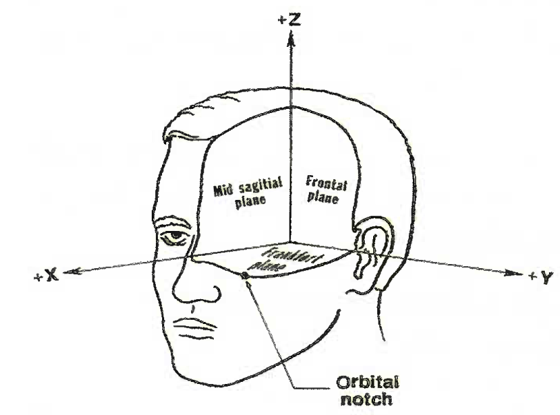
To evaluate the potential for an increase in the risk of neck injury during ejection and long duration WBV environment of helicopter flights while wearing a helmet and HMDs, mass properties measurement tests of the helmet systems were carried out. The weight and CG relative to the ATD head anatomical origin was measured on a Trifilar pendulum mass property instrument manufactured by M/S DEFSYS Pvt Ltd, Bangalore. The ATD head was designed and developed using Wood and Aluminium and it represented the mid-size 50th percentile population of the Indian male aviators [7, 8 & 21]. The anatomical origin of the head is cross section of Sagittal, Frankfurt and Coronal planes of the head. The Y- axis is a line connecting the right and left tragion (notch above ear canal), X-axis is a line connecting the infra-orbital notch and the Y- axis and shifted equidistantly between the tragion, and Z axis a line perpendicular to the intersection of the X and Y-axis as shown in Fig 1. The ATO head was fixed on to an orthogonal holding fixture so that it could be oriented along three orthogonal planes: XY, XZ, and YZ on trifilar pendulum (Fig 2).

- Mead anatomical coordinate system

- Holding fixture to facilitate referencing
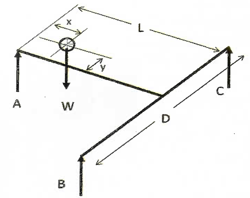
A trifilar pendulum based on torsion of strings, consisted of a movable plate suspended using 3 strings, each of length ‘L’ [22, 23]. Each string is linked to the top fixed plate through load cell that measured cable tension in real time [24]. The picture of trifilar pendulum, placement of load cell and suspension of strings is given in Fig 3. The load cells had a capacity 40 kg each and a least count was 5 gm. The orthogonal frame fixed with ATD head was placed on the trifilar pendulum platform for XY and YZ orientations as shown in Fig 4 and the load cell reading were recorded in each configuration. The mass of an object placed on the Trifilar system was simply sum of the tension in the strings as displayed In the load cells [8, 18 & 25]. The CG location coordinates were calculated using the principle of balance of mass moments by summing the moment about the reference load cell that was considered as pivot point. The sketch of balance of moment about reference load cell A is explained in Fig 5 [18, 25].

- Trifilar pendulum with string tension measurement and load cell setup

- XY and YZ orientations of ATD head-helmet assembly

- Balance of moments about reference load cell A
The X and Y CG coordinates are then calculated using:
Where,
A = Reference load cell
B = Tension in load cell cable B
C = Tension in load cell cable C
L = Perpendicular distance between A and BC
D = Distance between load cell B and C
W = Mass of the object on pendulum
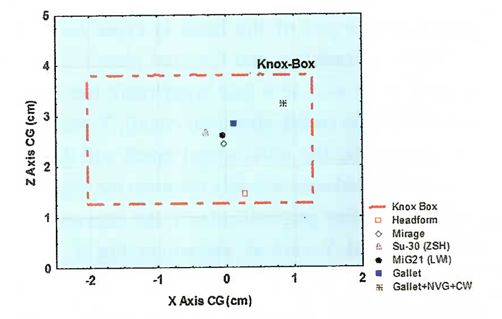
The coordinate transformation was done to refer the CG from ATD head origin. The helmets under study were fitted on to the ATD head in the same manner that the pilot wore them. The distance from ATD head sellion to front rim of the helmet was measured for record and use in repeat measurements (Fig 6). The visors were kept in stowed position. The CG measurement head-helmet was taken orienting the combination in X Y and YZ positions. A minimum of three measurements were made in each orientation with the helmet being removed and replaced between measurements. The multiple helmet removals and repositioning are conducted in an attempt to replicate minute, natural variations in the aviator helmet position that occur between repeated helmet donning and doffing cycles. Four standard medium sized flight helmets of Mirage-2000, Mig-21 (LWI), Su-30 and Gallet were used for the mass property measurement. The Gallet helmet was studied unmodified and configured with NVG and counter weight (CW). The combined head-helmet mass and CG coordinates were determined and the combination CG were plotted atop the Knox Box for assessing CG shifts (Fig 7).

- ATB Head sellion to helmet rim distance

- Combined ATD head-helmet CG location for four helmets in Knox Box
The neck torques viz weight moments and mass moments at head-neck joints were computed using following [10, 19].
Weight moment = Helmet weight * Longitudinal CG from C7/T1
Mass moment = Helmet weight * Vertical CG location from C7/T1
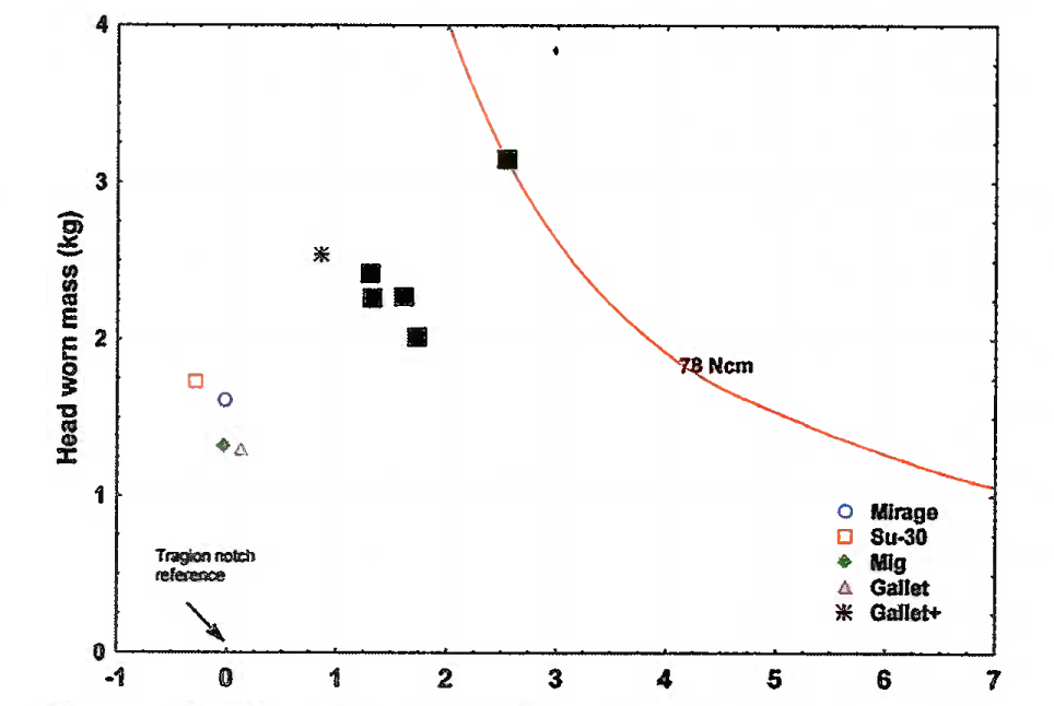
Vertical and longitudinal CG locations as a function of allowable head worn mass were plotted and injury assessment were carried out based on the constant mass moment concept acting about the C7/T1 juncture [19, 20, 26]. A comprehensive analysis of the data was performed using available injury predictors to identify maximum limits for helmet weight and CG and predict the likelihood of injury to the neck and upper cervical spine.
A summary of Inertial properties of the ATD head and helmets is shown in Table 1. The CG data for the ATD head, helmet as well as helmet assembly is relative to the head anatomical coordinate system. As compared to unmodified Gallet helmet having weight of 1.30 Kg, NVG and counter weight increased the total Gallet assembly weight by 1 25 Kg. For a frame of reference for the graph, the graph’s origin is located at the tragion notch with positive Z-axis directed toward the top of the head, add the positive X-axis towards the eyes. None of the helmets breached the acceptable limit of X and Z coordinate CG shift-defined by Knox boundary. However, Gallet assembly has a greater CG shift in the X-axis and Z axis compared to the unmodified Gallet helmet. For 50th %tile head/neck joint C7/T1 is located approximately at 2.2 cm backward and 11.95 cm below of the anatomical origin. The computed neck torques at the occipital condyle due to longitudinal and vertical CG shifts are shown in Table 2. Gallet assembly is heavier and has a large X-axis and Z axis moments. The longitudinal center of mass as a function of allowable head worn mass is given in Fig 8.
|
Headgear |
Mass (kg) |
CGx(cm) |
CGy(cm) |
CGz(cm) |
|---|---|---|---|---|
|
ATB Head |
3.33 |
0.28 |
-0.01 |
1.44 |
|
Medium Mirage (Visor stowed) |
1.61 |
-0.03 |
-0.11 |
2.45 |
|
Medium Su-30 (ZSH) (Visor stowed) |
1.73 |
-0.29 |
0.33 |
2.66 |
|
Medium Mig21 (LW1) (Visor stowed) |
1.32 |
-0.04 |
-0.08 |
2.59 |
|
Medium Gallet (No Additional cqpt) |
1.30 |
0.12 |
0.09 |
2.83 |
|
Medium Gallet +NVG +CW |
2.54 |
0.85 |
0.11 |
3.22 |
|
Headgear |
CGx_AOC |
Ã(N-cm) |
CGz_AOC |
Mass Moment(Kg-cm) |
|---|---|---|---|---|
|
ATB Head |
2.40 |
- |
- |
|
|
Mirage |
2.27 |
35.82 |
14.4 |
23.19 |
|
Su-30 (ZSH) |
2.01 |
34.08 |
14.6 |
25.26 |
|
Mig21 (LWI) |
2.26 |
29.24 |
14.53 |
19.18 |
|
Gallet |
2.42 |
30.83 |
14.77 |
19.20 |
|
Gallet+NvG+CW |
3.15 |
78.40 |
15.13 |
38.43 |

- Head/Neck CG longitudinal distance from tragion notch (cm)
Discussion
As expected, the mass of the medium Gallet flight helmet increased as NVG was added. The maximum allowable head supported at the C7/T1 juncture is 2.5 Kg for the given impact condition and includes the helmet, head, and neck mass. Standard Gallet helmet had weight of 1.30 Kg and that increased to 2.54 kg after adding NVG and counterweight. The result of the present study indicates that combined head helmet CG was within the Knox-Box boundary for all helmets. The size of the Knox- Box is a function of the helmet mass among other factors. Addition of the NVG and CW mass caused the CG of the helmet to shift forward (represented by a increase in X-axis CG location as compared to the unmodified helmet) and upward (indicated by an increase in Z-axis CG location). Though the mass of the Gallet appeared 0.27 kg heavier than recommended and there was considerable CG shift, it did not breach the Knox boundary limits. The X axis CG shift for all helmets except Galley assembly was posterior to tragion notch. The upward shift for standard Su-30 (ZSH) and standard Gallet were due to HMD mounting frames. For Su-30 (ZSH) helmet the Y axis CG shift of 0.33 cm could be because of placement of communication and other cables. The expansion/ compression of Knox-Box boundary is only on X- axis as the compression force magnitude is more sensitive to CG shifts in the Z axis than X axis. The acceptable boundary limits are for X and Z coordinate of the CG shift defined and Knox-Box Criteria does not includes the CG shift across the mid-sagittal plane. Meanwhile the CG shift across sagittal plane was negligible.
The longitudinal CG location changes of the helmeted head generating weight moments at head/ neck joint have greater effects on wearer fatigue and performance decrement. The weight moments represent the pitching moment about the lateral axis (the axis running from left ear to right ear through the tragion notch). A neck torque (weight moment) defined as biomechanical response of 82.8 ± 22.8 N-cm, measured about the AOC was recommended based on changes in head pitch accelerations and posterior neck EMG response. A vigilance response of 78 N-cm was suggested whereas the tolerance limit is 106.5 N-cm [19]. In the plot of longitudinal CG shift as a function of head worm mass, the solid black line represents a constant weight moment of 78 N-cm represented from the tragion notch. The variation in CG shift and helmet mass has to be such that the torque on the neck remains below this value. The solid black squares represent weight moment on C7/T1 juncture. The C7/T1 juncture was selected as the pivot point because it is more frequently injured in aircraft accidents than upper cervical vertebra. The torque as measured for C7/T1 juncture for the Mirage, Su-30, MiG-21 and unmodified Gallet fell below the 78 N-cm curve and clustered near 30 N-cm. The neck torque was on constant weight moment line for Gallet with NVG and CW assembly. Alem and Meyer (1995) have reported in their study that in long duration whole body vibration the aviator’s abilities to consistently track a moving target degraded (the amount of time needed to acquire and extinguish the target increased) at weight moments above 78 N-cm. Pilot would likely to experience the more levels of fatigue and discomfort if helmet weight moment is above the recommended limit.
The vertical center of mass limit is based on a constant mass moment concept acting about the C7/T1 juncture. The mass moment is a moment about C7/T1 head/neck juncture due to total head supported mass and distance of the vertical CG location above this juncture. The limiting value of the mass moment is 29.8 kg-cm. The minimum mass moment was 19.18 kg-cm for the MIG -21 (LWI) helmet. Even though the vertical CG shift for Mirage helmet was less than MIG, the weight of the Mirage helmet was higher than the MIG helmet. The mass moment at the lower head-neck joint due to Gallet assembly was 38.43 kg-cm which was 8.6 kg-cm higher than the recommended limit at C7/T1 juncture.
Conclusion
An accurate method for measuring mass property of ATD head and head encumbering devices has been developed at this Institute. Shift in the CG of the helmet wrt head CG was assessed. Aircrew flight helmets were tested for compliance with Knox-Box criteria and neck torque limits. Based on Knox-Box evaluation results, there appears to be no breach in the safety in any of the helmet configurations. As helmeted-head CG is within Knox permissible proximity to head CG, the injury potential due to CG shift during ejection or impact is negligible. Weight moments of the helmeted head were within the safe limit. However, mass moment of Gallet assembly was slightly higher than the recommended limit. This may result in pilot neck fatigue and difficulty in target tracking in operational conditions like long duration whole body vibrations.
References
- A literature review of musculoskeletal injuries to the human neck and the effect of head supported mass worn by soldiers. USAARL contract report no CR-2006-01.
- [Google Scholar]
- The effect of head supported mass on the risk of neck injury in army personnel. John Hopkins APL Technical digest. 2005;26
- [Google Scholar]
- To study the shift of Centre of Gravity in helmets with helmet mounted devices. AFMRC Project No 3133/02.
- [Google Scholar]
- Mass property and inertial loading effects of head encumbering devices. AAMRL-TR-88- 044.
- [Google Scholar]
- Cervical injury risk resulting from rotary wing impact. Technical report NAWADPAX/ TR-2004/86.
- [Google Scholar]
- Mass property test procedure for manikin head form and helmet systems. Final report NAWCADWAR-92692-60.
- [Google Scholar]
- Design and development of anthropometrically correct head form for joint strike fighter ejection seat testing. AFRL-HE-WP-TR-2005-0044.
- [Google Scholar]
- Effects of magnetic receiver unit (MRU) installation on the blunt impact protection of the HGU-56/P aircrew integrated helmet system (AIHS) USAARF-Report No. 10, 2009
- [Google Scholar]
- Neck torque study induced by head-borne visual augmentation systems (VAS) in ground-based applications. NSTD. :9-1007.
- [Google Scholar]
- Performance assessment of the HGU-84/P Navy helicopter pilot helmet. USAARL Report No. 96-041996.
- [Google Scholar]
- Vertical impact test of the X-31 helmet mounted visual and audio display (HMVAD) system. AL/CF-SR-1997-0008 Interim report.
- [Google Scholar]
- Vertical impact testing of two helmet mounted night vision systems. AL/CF-SR 1994-0013 Interim report.
- [Google Scholar]
- Evaluation of the combat edge and MBU-20/P mask system during +Gz impact acceleration. AL/CF-SR-1995-0005.
- [Google Scholar]
- Effects of head supported devices on pilot performance during simulated helicopter rides. USAARL Report No. :95-37.
- [Google Scholar]
- Vertical impact test of the panoramic night vision goggles. AFRL-HE-WP-SR- 1998-0006.
- [Google Scholar]
- Neck muscle fatigue resulting from prolonged wear of weighted helmets. AFRL-RH-WP-TR-2008-0096.
- [Google Scholar]
- A performance history of AN/PVS-5 and ANVIS image intensification system in US army aviation. USAARL Report No 98-28.
- [Google Scholar]
- Design & Development of anthropometric rigid head form for Centre of Gravity measurement of IAF flight helmets. Proceedings 51st ISAM Conference.
- A trifilar pendulum for the determination of moment of inertia. ASTIA Report R-1653.
- [Google Scholar]
- Determination of the Physical data of the head Centre of Gravity and Moment of Inertia of human heads. Office of Naval Research Scientific Report No. N000 14-75C-0486.
- [Google Scholar]
- Finding cadaveric human head mass and center of gravity: a Comparison of direct measurement to 3d modeling In: A thesis submitted at Wright State University. 2005.
- [Google Scholar]


