
Translate this page into:
Localization of center of gravity of helmet systems in the human anatomical frame using 3D laser scanners

*Corresponding author: Sabyasachi Nayak, Department of Human Engineering, Institute of Aerospace Medicine, Bengaluru, Karnataka, India. iamhephysics@gmail.com
-
Received: ,
Accepted: ,
How to cite this article: Nayak S, Sekhar MB, Tripathy NK, Joshi VV. Localization of center of gravity of helmet systems in the human anatomical frame using 3D laser scanners. Indian J Aerosp Med 2022;66:71-8.
Abstract
Introduction:
An accurate assessment of the Center of Gravity (CoG) and mass properties of aircrew helmets and helmet-mounted devices is an essential requirement to predict neck injury potential. Conventionally, trifilar pendulum method is used for the assessment of CoG shift and calculation of force moment and mass moment. In this study, a new procedure is described to obtain a more precise measurement of the CoG of the helmet as well as the combined head and helmet system.
Material and Methods:
Measurement of the helmet mass and CoG properties was done using a trifilar pendulum and the geometrical properties of the helmet and head were obtained using a 3D laser scanner. The required coordinate transformations from the laboratory frame to the anatomical frame using the 3D scanner as a coordinate digitizer. The head sizes used in the calculations ranged from small female head to large male head and a single average head CoG position was used to calculate the combined head and helmet CoG.
Results:
The error of the 3D scanner method for combined head and helmet CoG measurement as compared to the trifilar pendulum method varied between 0.3 mm and 0.4 mm with an average error of 0.4 mm. This method could also successfully calculate the combined CoG of the helmet on various head sizes ranging from small female to large male heads.
Conclusion:
The 3D laser scanner-based CoG measurement gave similar results as compared to the present method of CoG measurement when the medium-sized anthropomorphic test dummy head was considered. The localization of helmet CoG in the anatomical frame would allow more accurate measurements of force moment and mass moment. The same methodology could also be used to calculate the combined head and helmet CoG of different head and helmet masses.
Keywords
Center of gravity
Anatomical frame
Trifilar pendulum
3D Laser scanner
Coordinate digitization

INTRODUCTION
Aircrew helmet is a critical safety equipment, especially while flying fighter aircraft and helicopters. In addition to head protection, helmets also function as a mounting platform for various Helmet-Mounted Devices (HMDs) such as night vision goggles, helmet-mounted display systems, oxygen masks, and radio communication systems. The helmet along with these additional HMDs changes the original Center of Gravity (CoG) of the aircrew head and has the potential to affect both the crash and ejection safety.[1-3] It can also lead to neck fatigue on prolonged usage.[1-6] The two main factors known to affect the neck loads while wearing helmets are the total head supported mass and the combined CoG of the head-helmet system.[2,7] The two most commonly used criteria for determining helmet safety are the Knox-Box criteria[1] and the USAARL HSM Curves[5,6] for determining the force moment and mass moment thresholds. An accurate assessment of helmet mass properties and CoG of head-helmet system concerning the human head anatomical frame is an important requirement for the technical qualification of helmet during design stage.[2,7,8]
The presently used method for CoG measurement is the trifilar pendulum method. This method requires the use of an Anthropomorphic Test Dummy (ATD) head which represents the 50th percentile of Indian aircrew in terms of head mass. However, the ATD head is not a good representative of either the head dimensions or the head mass distribution (and hence the average head CoG) of the 50th percentile Indian aircrew, which is likely to introduce an error when calculating the combined head and helmet CoG. We propose a new methodology that uses the scanned 3D image of a real human head to correctly localize the helmet CoG concerning the head anatomical frame. This enables us to use the correct head dimensions as well as obtaining accurate head-helmet fitment, to calculate the combined head and helmet CoG as well as the force and mass moments.
MATERIAL AND METHODS
Subjects
Three non-aircrew volunteer subjects participated in the study. They were briefed about the procedure and an informed consent was taken. The relevant anthropometric head parameters of the subjects are given in Table 1.
| S. No. | Head length (cm) |
Head breadth (cm) |
Head circumference (cm) |
|---|---|---|---|
| Subject 1 | 20.9 | 16.3 | 58.8 |
| Subject 2 | 20.4 | 16.0 | 57.6 |
| Subject 3 | 20.8 | 15.1 | 60.1 |
Materials
The study was conducted at the Department of Human Engineering, Institute of Aerospace Medicine (IAM), Bengaluru, using the Helmet CoG Testing Facility and the Vitus 3D Laser Scanner. The helmet used in the study was a large size Light Weight Integrated Helmet (LWIH). The CoG was measured for various helmet configurations such as single/double visors in up/down positions and NVG stowed up/in-use positions.
Methodology
The CoG of the helmet in the box frame was measured using the Trifilar Pendulum Mass Property Measurement System.[1] The helmet was strapped to the ATD head affixed to an Orthogonal Support Box and readings were taken in the trifilar pendulum system to obtain the helmet CoG coordinates in the box frame. Thereafter, three scans were performed using the 3D laser scanner which included a 3D scan of (a) the helmet strapped to the ATD in the Orthogonal Box (Box + Helmet Scan), (b) the aircrew subject wearing the helmet (Helmet + Face Scan), and (c) the aircrew subject’s head (Face + Head Scan).
Markers were attached to various landmark points of interest on the box, helmet, and head, to record their x, y, and z coordinates in the laser scanner-based laboratory frame using the Anthroscan Software. These values were used to perform coordinate transformations between different frames. The coordinate frames of interest were the laboratory frame, the box frame, the helmet frame, the facial frame, and the anatomical frame. The coordinate frame defined concerning the laser scanner is called the laboratory frame and all the coordinates of the landmarks from the 3D scan image were obtained in the laboratory frame. The coordinate frames rigidly attached to the box, helmet, face, and head were defined as the box, helmet, facial, and anatomical frames. These are described later in the following subsections.
Some landmark points were common in two different scans. The helmet landmark points were measured in both the 1st and 2nd scans and the face landmark points were measured in both the 2nd and 3rd scans. Once the CoG coordinates were known in one scan, the same values were used in the subsequent scan using these common landmark points. Within the same scan, two coordinate transformations were performed, as shown in Figure 1, to transfer the helmet CoG coordinates from the box frame to the helmet frame and subsequently to the facial frame and finally to the anatomical frame. This process involved the calculation of the frame x, y, and z axis unit vectors from the laboratory frame coordinates, making them exactly perpendicular to each other using the Gram-Schmidt orthogonalization process, thus obtaining the rotation matrix and finally shifting and rotating the CoG from one frame to the subsequent frame. The detailed calculations are given in the calculations section. The final result of this procedure was the coordinates of the helmet CoG in the anatomical frame. Finally, the combined head and helmet CoG were calculated for various head masses ranging from small female to large male head, using the average values for head CoG coordinates in an anatomical frame as reported in the literature.[9-12]

- Methodology: Flowchart of the scans and coordinate transformations to obtain helmet Center of Gravity (CoG) in Anatomical frame from helmet CoG in box frame. I/p: Input parameter, O/p: Output parameter. Note: After each scan, the laboratory coordinates of the landmark points were recorded and two coordinate transformations were done. The CoG coordinate transfers are shown using thick blue arrows.
Calculations of CoG
The four steps followed for calculations are described below:
Step 1: Helmet CoG measurement concerning the orthogonal support box
The first step was to measure the CoG coordinates of the helmet concerning an Orthogonal Support Box. This was done using a trifilar pendulum, following the method of Gaur et al.[1] The CoG coordinates of the helmet concerning the trifilar pendulum coordinate frame were calculated, which were then translated to the box frame. To obtain the CoG of the helmet, the readings of the three load cells were measured with the helmet strapped to the ATD head affixed within the Orthogonal Support Box from which the reference load cell values of the box and ATD contribution were subtracted. Using the balance of moment formula,[1] the CoG coordinates concerning the trifilar pendulum frame were obtained, and by doing a simple shifting of coordinates, the CoG coordinates concerning the box frame (xCoG,B, yCoG,B, and zCoG,B) were calculated.
Step 2: Scanning and recording the box and helmet marker coordinates
For the first scan, a marker was attached to the origin of the box frame and additional markers were attached to define the x, y, and z axes of the box frame. Markers were also placed on the side landmarks/screws of the helmet, helmet vertex point (topmost point along helmet z-axis), and helmet center landmark point. After scanning the helmet strapped to the ATD head in the Orthogonal Box, the marker coordinates concerning the laboratory frame were recorded. Here, the first coordinate transform was performed from the laboratory frame to the box frame.
For the first coordinate transformation, two sub-transformations were applied: A coordinate translation followed by a coordinate rotation. A general rigid body coordinate transformation can be represented as a shift or translation followed by a rotation.[7,13] For the translation step, the coordinates of the box origin as measured in the laboratory frame were subtracted from the coordinates of all other points of interest which had markers attached to them. This resulted in an intermediate coordinate system with origin coinciding with the box origin, but x, y, and z axes aligned with the laboratory frame. To go from the lab axes to the box axes, all the intermediate coordinates of the points of interest were multiplied by a rotation matrix.[13] The rotation matrix for this second step of the coordinate transformation required the unit vectors along the box x, y, and z axes. To obtain these unit vectors, the markers along the x, y, and z axes of the box frame were used. The vector along the box x-axis was derived by taking the difference of the coordinates of two markers placed along the box x-axis. The unit vector along x-axis was computed by dividing this vector by its magnitude, which was a triplet of numbers (x1, y1, and z1). A similar process for the box y-axis and z-axis markers obtained the values for the y-axis and z-axis unit vectors (x2, y2, z2) and (x3, y3, z3). In general, these vectors might not be exactly perpendicular to each other and by following the process of Gram-Schmidt orthogonalization,[14,15] a set of unit vectors that were precisely perpendicular to each other were derived. This process is illustrated in Figure 3. If the coordinates of the orthogonal unit vectors for box x, y, and z axes were (bx1, by1, bz1), (bx2, by2, bz2), and (bx3, by3, bz3), then the rotation matrix would be the following 3 × 3 matrix:
The box frame coordinates (xB, yB, zB) of a point having laboratory frame coordinates (xL, yL, zL) would be:
where, (xBO, yBO, zBO) were the laboratory frame coordinates of the box origin.
This calculation was done for all the landmark points on the helmet to get a list of coordinates in the box frame. Helmet CoG in the box frame (xCoG,B, yCoG,B, zCoG,B), which was measured using the trifilar pendulum, was appended to this list.
In the second coordinate transformation, the coordinates of the helmet landmark points and helmet CoG in the box frame as obtained from the last step were transformed to the helmet frame. The midpoint of the two helmet side landmarks was chosen as the helmet origin, the line from the helmet origin to helmet vertex point was chosen as the intermediate z-axis, and a line from the helmet origin to the helmet left side landmark was chosen as the intermediate y-axis. Using the helmet center landmark point as the third point, a Gram-Schmidt orthogonalization process was carried out to give three mutually perpendicular unit vectors that define the helmet x, y, and z axes. This defined the rotation matrix. The helmet landmark points and the helmet CoG coordinates were converted from the box frame to the helmet frame using a shift to the helmet origin followed by a rotation to the helmet axes. The helmet frame coordinates (xH, yH, zH) of a point having the box frame coordinates (xB, yB, zB) would be as follows:
Here (xHO, yHO, zHO) were the coordinates of the helmet origin in the box frame and (hx1, hy1, hz1), (hx2, hy2, hz2), and (hx3, hy3, hz3) were the orthogonal unit vectors along helmet x, y, and z axes. Applying this formula to the helmet CoG coordinates in the box frame (xCoG,B, yCoG,B, zCoG,B) as calculated in the last step allows us to obtain these coordinates in the helmet frame (xCoG,H, yCoG,H, zCoG,H) as:
Step 3: Scanning and recording the helmet and facial marker coordinates
The second scan was carried out by scanning the helmet worn on the head of the subject Figure 2, with markers placed on the helmet landmarks and the subject’s sellion, chin, and right and left infraorbitale. The respective laboratory coordinates were recorded. This enabled to transform the helmet CoG as measured in the helmet frame to a coordinate frame attached to the subject’s face which could be called the facial frame. The facial frame had its origin at the sellion and the x, y, and z axes were in the aft-to-fore, right-to-left, and down-to-up directions, respectively. First, using a coordinate shift and rotation from the laboratory frame to the helmet frame, the facial landmarks were transformed from the laboratory to helmet frame. This was used to define the facial frame. The laboratory frame to helmet frame coordinate transformation could be expressed mathematically as follows:

- (a-d) Images of the laser scanner setup before the scans, showing the positions of the markers at the landmark points.
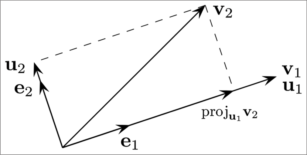
- Gram-Schmidt orthogonalization: Given three non-coplanar vectors , and , the Gram-Schmidt process returns three mutually perpendicular unit vectors , , and . The first two vectors are shown here.
Again, using a shift and rotation transform, the helmet CoG was transformed from the helmet frame to the facial frame. The helmet frame to facial frame coordinate transformation could be expressed mathematically as:
where, (xFO, yFO, zFO) were the facial origin (Sellion) coordinates in helmet frame. Applying this formula to the helmet CoG coordinates in the helmet frame (xCoG,H, yCoG,H, zCoG,H), as shown below, the helmet CoG in facial frame (xCoG,F, yCoG,F, zCoG,F) was obtained:
Step 4: Scanning and recording the facial and head marker coordinates
The third scan involved scanning the subject’s head with landmarks placed at the facial reference points (sellion, chin, and right and left infraorbitale) as well as the head landmarks, namely, the right and left tragions and their laboratory coordinates were recorded. The anatomical frame was defined with the origin at the anatomical origin, which had been defined to be the midpoint of the right and left tragions. The anatomical x-axis was defined to be along a line from the anatomical origin to the midpoint of the right and left infraorbitale. The anatomical y-axis was defined to be along a line from the anatomical origin to the left tragion. The third point was taken as the sellion and another Gram-Schmidt orthogonalization process was carried out to define a set of three mutually perpendicular x, y, and z axes unit vectors, thereby defining the aanatomical frame. Then, a coordinate transform was carried out transforming the facial and head landmarks from the laboratory to facial frame. The laboratory frame to facial frame coordinate transformation could be expressed mathematically as follows:
Finally, the last coordinate transform was carried out to transform the helmet CoG from the facial frame to the anatomical frame. The facial frame to anatomical frame coordinate transformation can be expressed mathematically as:
where, (xAO, yAO, zAO) are the anatomical origin coordinates in the facial frame. Applying this formula to the helmet CoG coordinates in the facial frame (xCoG,F, yCoG,F, zCoG,F) derived the helmet CoG in anatomical frame (xCoG,A, yCoG,A, zCoG,A) as below:
This completed the process to finalize the position coordinates of the helmet CoG (xCoG,A, yCoG,A, zCoG,A) = (xHelmet, yHelmet, zHelmet), with respect to the anatomical frame. Finally, the combined head and helmet CoG in the anatomical frame was calculated. For this, the average head mass and the average location of the head CoG were needed. The average head mass, mHead, was taken as the head mass of the 50th percentile Indian male aviator, which was the same as the mass of the medium size ATD, equaling 3.77 kg.[1] The same calculation was also repeated for the head sizes of small female head (mass = 3.36 kg), mid-size female head (mass = 3.67 kg), mid-size male head (mass = 4.26 kg), and large male head (mass = 4.99 kg) to obtain the CoG location for each case.[9] The average head CoG location with respect to the anatomical origin was as follows:
(xHead, yHead, zHead) = (0.83 cm, 0 cm, 3.12 cm)
Here, the average head CoG was 0.83 cm to the fore and 3.12 cm upwards of the anatomical origin.[10] Using these values, the combined helmet and head CoG (xCoG, yCoG, zCoG) could be calculated as the mass weighted average of the head CoG and helmet CoG:
Calculations of measurement error
The measurement error was defined to be the Euclidean distance between the CoGs measured using the two methods, namely, CoG measurement using the trifilar pendulum and subsequently the measurement using the 3D laser scanner. If the X and Z CoG positions as measured using the trifilar pendulum method were CGXT and CGZT and those for the laser scanner method were CGXL and CGZL, then the error is defined as follows:
This was measured for four helmet configurations of the large LWIH: (a) both visors stowed, (b) clear visor down, (c) dark visor down, and (d) both visors down.
RESULTS
The CoG measurements for each configuration measured using both the methods are shown in Table 2. The average error for the four measurements was around 0.4 mm.
| Helmet | Trifilar pendulum | 3D laser scanner | Error | ||
|---|---|---|---|---|---|
| Configuration | CGXT(cm) | CGZT(cm) | CGXL(cm) | CGZL(cm) | Error (cm) |
| Both visors stowed | 0.105 | 3.481 | 0.144 | 3.468 | 0.04 |
| Clear visor down | 0.141 | 3.408 | 0.169 | 3.391 | 0.03 |
| Dark visor down | 0.138 | 3.381 | 0.165 | 3.366 | 0.03 |
| Both visors down | 0.279 | 3.290 | 0.284 | 3.251 | 0.04 |
The combined head and helmet CoG for four different helmet configurations calculated using various head sizes (small female, mid-sized female, mid-sized male, large male, and medium ATD head) are depicted in Table 3.
| Helmet configuration: | Both visors stowed | Clear visor down | Dark visor down | Both visors down | ||||||||
|---|---|---|---|---|---|---|---|---|---|---|---|---|
| xHelmet | yHelmet | zHelmet | xHelmet | yHelmet | zHelmet | xHelmet | yHelmet | zHelmet | xHelmet | yHelmet | zHelmet | |
| Helmet CoG (anatomical coordinates) [cm] |
−1.54 | 0.04 | 4.32 | −1.45 | 0.14 | 4.06 | −1.46 | 0.25 | 3.97 | −1.05 | 0.09 | 3.57 |
| Head+helmet CoG (anatomical coordinates) [cm] |
xCoG | yCoG | zCoG | xCoG | yCoG | zCoG | xCoG | yCoG | zCoG | xCoG | yCoG | zCoG |
| Head mass [kg] | ||||||||||||
| Small (F) (3.36) | 0.09 | 0.01 | 3.50 | 0.11 | 0.04 | 3.41 | 0.11 | 0.08 | 3.39 | 0.24 | 0.03 | 3.26 |
| Mid (F) (3.67) | 0.13 | 0.01 | 3.48 | 0.16 | 0.04 | 3.40 | 0.15 | 0.07 | 3.37 | 0.27 | 0.03 | 3.25 |
| Mid (M) (4.26) | 0.20 | 0.01 | 3.44 | 0.22 | 0.04 | 3.37 | 0.22 | 0.07 | 3.35 | 0.33 | 0.02 | 3.24 |
| Large (M) (4.99) | 0.27 | 0.01 | 3.40 | 0.29 | 0.03 | 3.34 | 0.29 | 0.06 | 3.32 | 0.39 | 0.02 | 3.23 |
| Medium ATD (3.77) | 0.14 | 0.01 | 3.47 | 0.17 | 0.04 | 3.39 | 0.17 | 0.07 | 3.37 | 0.28 | 0.03 | 3.25 |
CoG: Center of gravity, ATD: Anthropomorphic test dummy
DISCUSSION
The importance of CoG analysis of helmets along with HMDs is to estimate the neck loads during exposure to ejection or crash forces as well as to estimate neck strain during long duration flights.[1-6] At present, this is done at IAM using the Trifilar Mass Property Measurement System using ATD headforms as substitute for the mid-sized (50th percentile) and large-sized (95th percentile) heads.[1] The 3D laser scanner method can be used do the same assessment using a laser scanner to measure the geometrical relationship among the box, helmet, and anatomical landmark points and hence enable the translation and localization of the CoG in the anatomical frame.
The main advantage of the laser scanner method over the trifilar pendulum method is that the former enables one to localize the helmet CoG and combined head and helmet CoG with respect to an actual anatomical head. The trifilar pendulum method can only measure the combined head and helmet CoG using an ATD headform which may not correspond to an anatomical head in either the position of the head CoG or the actual dimensions of an anatomical head. This limitation of the trifilar pendulum method can be overcome by scanning the anatomical head of a human subject with and without the helmet by attaching appropriate landmark points, thereby obtaining the required coordinate transformations between the helmet and anatomical coordinate systems.
The laser scanner method is similar to the method of Shipley et al.,[7] but differs in some important aspects. First, by treating the facial landmark points as part of a separate and intermediate coordinate frame rather than just reference points common to the helmet and anatomical frames, the error in the CoG position is reduced. The error induced is larger on applying the Gram-Schmidt process to nonorthogonal frames, but the facial frame is just another intermediate orthogonal coordinate frame and hence reduces the error. Second, in the laser scanner method, one performs consecutive coordinate transformations from the box frame to the helmet frame to the facial frame and finally to the anatomical frame, instead of a back and forth transformation as used by the method of Shipley et al.[7] By reducing the number of numerical operations, the overall error in the CoG position is reduced as well. Third, using a 3D scanner instead of a coordinate digitizer, the coordinates of all points of interest could be permanently recorded, which could be referred to anytime in the future for any further calculations as required, and the whole experiment need not be repeated to do the CoG analysis. This also allows the storage and direct comparison of different helmets as and when the need arises.
The limitation of the laser scanner method is the assumption of a single head CoG for all head sizes in the anatomical frame, which can be easily overcome using different head CoG values for small female, mid-sized male and female, and large-sized male heads from the literature.[9-12] Another limitation of this method is that the 3D scans of the required objects can often be patchy, hence requiring multiple scans for getting coordinates of the landmark points. This can be overcome using a high resolution 3D head scanner.
CONCLUSION
The accuracy of the method of CoG measurement using a 3D laser scanner could be validated by taking the head mass as mass of the medium-sized ATD head and comparing it with the values obtained using only the trifilar CoG measurement system. These methods gave consistent values and the distance between the two CoG measured using the two methods was between 0.3 mm and 0.4 mm, with an average error of about 0.4 mm for four different measurements. Apart from this, it was also able to measure the combined head and helmet CoG for various head sizes ranging from a small female head to large male head when wearing the helmet. Measuring the distance between the head CoG and helmet CoG more accurately using a real human head allowed for a more precise measurement of the force and mass moments, though a more detailed study is required to validate this claim.
Declaration of patient consent
Patient’s consent not required as there are no patients in this study.
Conflicts of interest
There are no conflicts of interest.
Financial support and sponsorship
Nil.
References
- Determination of helmet CG and evaluation of neck injury potentials using “Knox Box criteria” and neck torque limits. IJASM. 2013;57:37-44.
- [Google Scholar]
- Biodynamic Testing of Helmet-mounted Systems. In: Proceedings of the Human Factors and Ergonomics Society 37th Annual Meeting. Vol 37. United States: SAGE; 1993. p. :79-83.
- [CrossRef] [Google Scholar]
- Neck Muscle Fatigue Resulting From Prolonged Wear of Weighted Helmets, Air Force Research Laboratory, Wright-Patterson AFB, OH, Report No. AFRL-RH-WP-TR-2008-0096. 2008
- [Google Scholar]
- Inertial properties of football helmets. J Biomech Eng. 2018;140:4039673.
- [CrossRef] [PubMed] [Google Scholar]
- Mass properties comparison of dismounted and ground-mounted head-supported mass configurations to existing performance and acute injury risk guidelines. Mil Med. 2019;184:245-50.
- [CrossRef] [PubMed] [Google Scholar]
- Mass Requirement of Helicopter Aircrew Helmets. USAARL Report No. 98-14 1998
- [CrossRef] [PubMed] [Google Scholar]
- Measurement of Mass and CG Location of Helmet Systems. In: Proceedings of the Human Factors and Ergonomics Society Annual Meeting. Vol 37. United States: SAGE; 1993. p. :74-8.
- [CrossRef] [Google Scholar]
- Proposed Standard for Measuring Head-Supported Mass Properties. USAARL, Fort Rucker AL, Report No. USAARL-TECH-TR--2020-052.
- [Google Scholar]
- Design and Development of Anthropometrically Correct Head Forms for Joint Strike Fighter Ejection Seat Testing. Wright-Patterson AFB. OH. Report No. AFRL-HE-WPTR-2005-0044 2005
- [Google Scholar]
- Center of Gravity and Moments of Inertia of Human Heads. In: England: Proceedings 5th International IRCOBI Conference on the Biomechanics of Impact. 1980. p. :228.
- [Google Scholar]
- Physical properties of the human head: mass, center of gravity and moment of inertia. J Biomech. 2009;42:1177-92.
- [CrossRef] [PubMed] [Google Scholar]
- Finding Cadaveric Human Head Mass and Center of Gravity: A Comparison of Direct Measurement to 3D Modeling In: A Thesis Submitted at Wright State University. 2005.
- [Google Scholar]
- Classical Mechanics. (3rd ed). Boston: Addison Wesley; 2002. p. :139-43.
- [CrossRef] [Google Scholar]
- Linear Algebra: Theory and Applications Sudbury, MA: Jones and Bartlett; 2009. p. :544-58.
- [Google Scholar]
- Gram-schmidt orthogonalization by gauss elimination. Am Math Mon. 1991;98:544-9.
- [CrossRef] [Google Scholar]


