Translate this page into:
Mathematical model for accurate measurement of head movements in simulators with frontal field visual display
Abstract
Modern Simulators in the Aeromedical environment incorporate large frontal visual field displays. This requires the monitoring camera within the simulator cockpit to be placed eccentrically. The resulting “off-axis” view causes problems in accurately determining the degree of head movement of subjects seated within the simulator. In this paper the author proposes a mathematical model relating the angle of eccentricity of the camera with the angle of head movement actually performed in the roll and pitch planes and the angle of head movement seen on the screen at the control panel. Use of this model would enable precise assessment of head movements within the Simulator for training as well as research purposes.
Keywords
Mathematical model
Simulators
Head movement angles

Introduction
In the aerospace environment, from a simple Barany’s chair to the latest 6° of freedom advanced Disorientation Simulator and the High Performance Human Centrifuge (HPHC) many simulators are mounted on rotating platforms. Head movements in a rotating environment give rise to bizarre vestibular responses, the intensity of which is dictated by a number of factors including the angle through which the head is and the rate at which it is tilted. Due to the presence of a large screen covering the visual field, any monitoring camera placed within the simulator cockpit is placed away from the mid-saggital plane of the subject as shown in Figure 1. This provides the operator observing on the Visual Display Unit (VDU) at the control panel with an “off-axis” view of the subject. An experienced operator may estimate the degree of head tilt but it still remains a subjective estimate. This skewed view is caused solely by the angle of eccentricity of the camera placement and hence it is possible to derive a mathematical relationship between:-
Angle of eccentricity of the camera
Angle of actual head movement
Angle of head movement as seen on the VDU

- Eccentric Position of camera within Simulator
This paper proposes a mathematical model for calculation of this relationship for a subject seated in a simulator cabin with an eccentrically placed camera.
Simulated rotatory environments in Aerospace medicine
Simulators utilise a rotatory environment for generating many physiological effects of vestibular origin. Motion sickness desensitisation programs play an important role in any air force in mitigating persistent airsickness in upto 14.6% of ab-initio pilots [1]. Graded training of the vestibular system involves use of Coriolis cross coupled sensations generated by head movements inside simulators mounted on rotating platforms and this has been studied extensively [2,3,4]. In these studies the standardization and accuracy in measurement of head movements is a subjective assessment by the operator and thus is liable to be contaminated with inter-subject and inter-operator variations. The human centrifuge simulating accelerative forces and the short arm centrifuge simulating artificial gravity in space present us with a rotatory environment. An area of focus in space research lies in mitigating or minimising the nausogenic vestibular response associated with a short arm centrifuge. Except for a few simulators with magnetic head tracker units [5,6] most do not have a system for accurate measurement of head movements being performed while in the simulator cabin.
Relevance of measurement of head movements
Head movements in a rotating environment lead to stimulation of the vestibular system by two non-coplanar angular motions and produce what is known as the Cross-Coupled Stimulus (CCS) [4].
The physiological interpretation of the CCS leads to the perceived angular velocity being a sine function of the angular velocity of the rotating platform ω (Omega) and the degree of head turn θ (Theta) as seen in the Equation given by Benson [7].
This equation shows that there are two components that determine the resultant angular velocity perceived by the higher centres. One is the angular velocity of the rotating platform denoted by ω and the angle through which the head moves denoted by θ. The angular velocity of the platform is precisely determined by the equipment itself but the angle of head movement is subject dependant and there exist practical problems in assessment of this angle. Hence it is essential to provide a generalised solution for measurement of accurate head movements of the subjects within the simulator cabin. In order to achieve this, a mathematical model was developed by the author, which is described below.
Mathematical Model and derivation
For a mathematical analysis of head movements in a three dimensional space it is essential to define a reference coordinate system to specify head position and movement and their mathematical relations. In this model, the Cartesian Coordinate Space has been used where the Yaw plane is represented by the x, y planes, the Roll plane by the x, z planes and the Pitch plane by the y, z planes as depicted in Figure 2. The Point of Origin (0,0) for the calculations has been fixed at the bottom right corner of the VDU at the control panel.

- Intersecting Planes in Cartesian coordinate system
In the three dimensional space of a simulator cockpit, a “head on” view of the subject would be produced if the plane of head movement and the plane of the camera were parallel to each other as depicted in Figure 3. But an eccentric position of the camera causes the plane of the head movement and the plane of the camera to be non-parallel. In this situation not only does the angle subtended by each point on the subject’s face change with head movement, but also the rate of change is different for each part of the face giving rise to a ‘dynamic skew’ where each point changes logarithmically. This makes assessment of change angle exponentially different, as shown in Figure 4. This deviation is solely caused by the angle of eccentricity of the camera and hence it is possible to derive a mathematical relationship between the incident point on the Head Movement Plane, the emergent point on the Camera plane and the angle between these two planes.
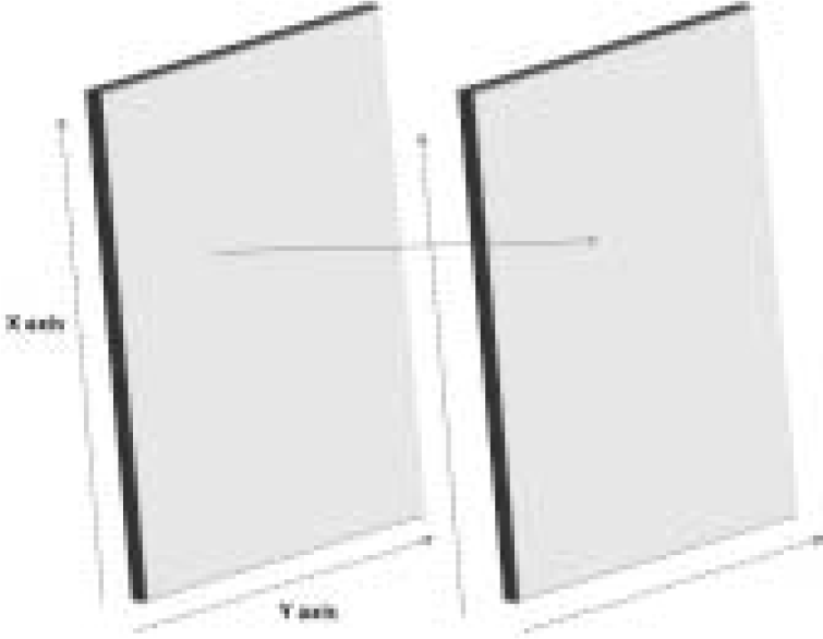
- Head Movement plane and Camera plane Parallel
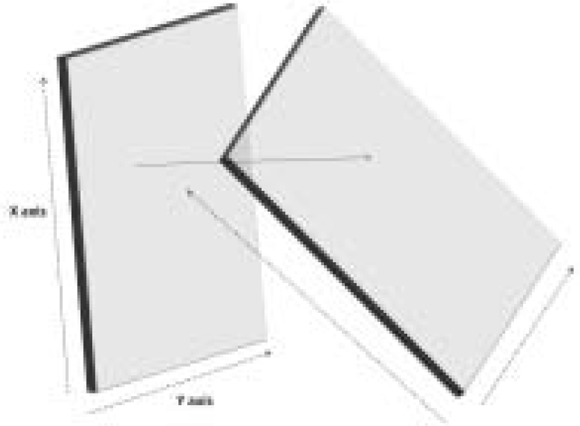
- Head Movement plane and Camera plane non-parallel
A diagrammatic representation of the head movements in the Roll plane is illustrated in Figure 5, 6. The Mathematical relationship for a head movement in the roll plane is:
Angle on left = 180-(actual head movt + Eccentricity of camera)
Angle on right = Eccentricity of camera – Actual head movt

- Movement in Roll plane seen from mid saggital plane

- Movements in Roll plane seen from camera plane
A diagrammatic representation of movements of the head within the simulator in the Pitch plane is depicted in Figure 7,8. The mathematical relationship for movements of the head in the pitch plane is:
Angle Fwd = 180-(actual head movt + Eccentricity of camera)
Angle Backward = Eccentricity of camera – Actual head movt

- Movement in Pitch plane seen from left coronal plane

- Movement in Pitch plane seen from camera plane
The mathematical derivation for both the equations along with diagrams is given in Appendix.
In a platform rotating on its Z axis hence a movement in the yaw plane would be coplanar. Such a movement is unlikely to have great significance in vestibular related experiments.
For a given system the degree of eccentricity of the camera is fixed. The degree of actual head movement required can be substituted in the equations and the result would be the apparent angle through which the head moves on the screen. This mathematical model in the form of a linear first order equation is relatively simple to incorporate into any software. A simple software for demonstration of automatic angle correction has been developed using Microsoft Excel→ and a screenshot of the same can be seen in Figure 9. This would enable the operator to verbally guide a subject to perform precise degrees of head movements within the simulator.

- Screen shot of Microsoft Excel sheet. Left side shows a 45 degree head movement and a camera angle of 60 degrees. In-built table shows the relation between coordinates X and Y based on the Mathematical model. Graph on the right shows line drawn on Visual Display Unit depicting predicted head movement angles based on mathematical model.
Discussion
Alternate approaches to applying this mathematical model would be to use software for face recognition and to provide a weighted mean of the points identified on the face as the midline for the head of the subject on which real-time analysis for head movement can be performed while correcting for the eccentricity of the camera using the given equations. Another approach would be to use a face recognition software to prepare a 3D mask of the subjects face and correct the eccentricity of the camera using the equations so that the final image presented to the operator at the VDU is a head-on view. These methods would also allow for real-time calculation of the degree as well as angular velocity of head movements.
For existing simulators this can be implemented without modifying the core system by taking a parallel video output from the simulator camera and subjecting the image to the above mentioned software manipulations on a separate PC based platform.
The simulators mounted on rotating platforms are used for training as well as research purposes. During training, the demonstration of vestibular effects by head tilts requires the accuracy of degree of head movement to be just measured to a level of being supra-threshold. But for research purposes the degree as well as the angular velocity of head movement needs to be objectively measured and reproduced to a fairly high degree of fidelity without inter-operator and inter-subject variability [4,5,6]. Without such objective and accurate means [3,8] the results and conclusions of any research stand suspect. The accuracy of head movement measurement is also underlined in the fact that current research in vestibular physiology shows the severity of nauseogenic effect of cross-coupled rotation to be directly proportional to gyroscopic angular acceleration [4]. Airsickness desensitisation programs around the world follow a combination of sequential and incremental training where various components of the conflicting stimuli are addressed separately and incremented individually [1,9,10]. Currently only the component of tangential acceleration provided by the rotatory platform is incremental in nature. A system with capability of accurate measurement of head movement opens avenues for incremental adaptation in the gyroscopic angular acceleration i.e. the degree of head movement and the velocity of head movement.
Conclusion
Anything in the physical or biological world, whether natural or involving technology and human intervention, is subject to analysis by mathematical models if it can be described in terms of mathematical expressions [11]. This simple mathematical model could be employed for measurement of head movement angles in the simulators wherein the large visual displays force the monitoring camera to be placed eccentrically. Software manipulation using the mathematical model equations performed on the analog or digital feeds from the monitoring camera would provide an immediate solution without intervening in the operating system of the Simulator.
Derivation

References
- Air sickness in trainee aircrew of Indian Air Force: Our experience with desensitisation. Ind J Aerospace Med. 2005;49(2):33-40.
- [Google Scholar]
- The desensitisation of chronically motion sick aircrew in the Royal Air Force. Aviat Space Environ Med. 1985;56:1144-51.
- [Google Scholar]
- Effect of direction of head movement on motion sickness caused by Coriolis stimulation. Aviat Space Environ Med. 1997;68:93-8.
- [Google Scholar]
- The severity of nauseogenic effects of cross-coupled rotation is proportional to gyroscopic angular acceleration. Aviat Space Environ Med. 1996;67:325-32.
- [Google Scholar]
- Aviation spatial orientation in relationship to head position and attitude interpretation. Aviat Space Environ Med. 1997;68:463-71.
- [Google Scholar]
- Aviation spatial orientation in relationship to head position, attitude interpretation, and control. Aviat Space Environ Med. 1997;68:472-8.
- [Google Scholar]
- Coriolis cross-coupling effects: Disorienting and nauseogenic or not? In: Naval aerospace medical research laboratory naval air station Pensacola. 1976.
- [Google Scholar]
- Physiological responses to the Coriolis illusion: effects of head position and vision. Aviat Space Environ Med. 2007;78:985-9.
- [Google Scholar]
- Incremental exposure facilitates adaptation to sensory rearrangement. Aviat. Space Environ. Med. 1978;49(2):362-64.
- [Google Scholar]
- Progressive adaptation to Coriolis accelerations associated with 1-rpm increments in the velocity of the slow rotation room. Aerospace Med. 1970;41(1):73-9.
- [Google Scholar]
- Mathematical model In Encyclopædia Britannica. Online 2008 Retrieved 27-082008, http://www.britannica.com/ebchecked/topic/369135/mathematical-model
- [Google Scholar]
Appendix
Mathematical derivation of relationship between actual head movement angle, angle of eccentricity of camera and angle of head movement seen on the VDU
In Figure 10, the two planes of interest, the coronal plane of the subject depicted by blue axis (Head Movement plane) and the plane of the camera depicted in maroon are superimposed upon each other at an angle at which they intersect each other in their (z) axis.

- Camera plane in maroon superimposed on Mid-saggital plane in blue showing various angles.
Therefore from (4) and (5) it can be seen that
Angle on left = 180-(actual head movt + Eccentricity of camera)
Angle on right = Eccentricity of camera – Actual head movt
A similar mathematical relationship can be derived for the movements of the head in the pitch plane. In Figure 11, the two planes of interest, the saggital plane of the subject depicted by blue axis (Head Movement plane) and the plane of the camera depicted in maroon are superimposed upon each other at an angle at which they intersect each other in their (z) axis
Angle Fwd = 180-(actual head movt + Eccentricity of camera)
Angle Backward = Eccentricity of camera – Actual head movt

- Camera plane in maroon superimposed on coronal plane in blue showing various angles.


